Capacity of 16000 m3/hr.
Total cost of 112,301,897 USD
NABE ALMEENA executing ALNAJAF – KUFA WATER TREATMENT PROJECT of capacity of 16000 m3/hr. to satisfy ALNAJAF &KUFA needs of tap water
Project divided into three main sections
1-Low Lift pump station
2-Water Treatment main plant
3-Booster pump station
4-Transfeering pipe line
Water treatment main plant consist of Distribution well, fast mixing 4 no. , Clarifiers of 38 m diameter 16 no. , 4 Ground storage tanks of 64*64 m2, 80 filters and back wash system.
Inlet channel and outlet channel, main pump station, power house.
In addition to Sludge pit , Chemical treatment workshop.
Administration Building and engineer and operators housing
1- Low Lift pump station
Its position on Euphrates River bank about 3 km from main treatment plant consist of pipes inside the river and pumps which sucking water and pump it to the treatment plant of 11 meters depth and 50 meters inside the river stream, Using 2No. of pipes of 1400 MM diameter fed by 9 pumps 6 operate and 3 standby each of 2800 M3/Hr Low Voltage ,supplying required amount of raw water i.e. 16000 M3 per Hr.
2- Inlet channel
Constructed from reinforced concrete provided with inner walls to reduce pumping pressure and accumulating quantity of water to be distributed to clarifiers
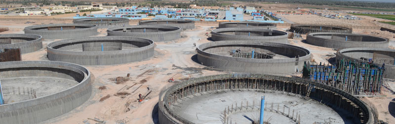
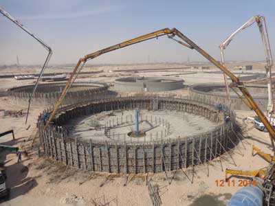
3- 16 No. circular clarifiers
Each 4 circular settling tanks of 38 meter diameter and 5 meter height provided with one distribution tank feeding raw water, settling tanks supplied with rotating scraper to drive settled sludge to pit at center which collect the sludge then sent to sludge pit house to returned to the river the upper part of scraper will collect the floating subjects
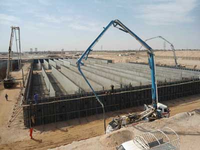
4- 80 No. filters
Filters constructed from reinforced concrete in 8 groups each have 10 cells provided with filter media consist of different sizes of gravels and layer of fine sands at the bottom an air pipe with nozzles for back wash erected, water comes out to collecting tank pumped out to inlet channel and then to ground storage tanks
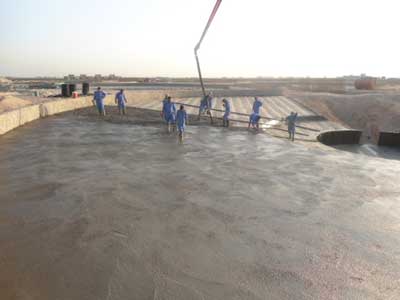
5- 4 No. Ground storage tanks
Each storage tank of 64 X64 meter of 5 meter height with 11 baffle walls inside the tank with one pipe of 1600mm feeding the GST and one pipe of 1600mm feeding the outlet channel which have 13 outlet pipes going to pumping house.
6- Outlet channel
Reinforced Concrete constructed distributing tank have 4 inlet pipes coming from GST’s to distribute over 13 outlet pipes each connected to high voltage high pressure Centrifugal double entry Motor – Pump from there to supply Najaf city Z1, Z2 other pipe feeding booster pump station .
7- Booster Pump station
Have an inlet channel and 4 Ground storage tanks and outlet channel connected to pump house provided with high voltage high speed Motor- Pump to feed Kufa city with tap water.
8- Chemical Building
It contains many cells for mixing chemicals with water and transfer to settling tanks which purifying water from contaminations , also there is Dosing pumps which pumping Chlorine gas for sterilization process .
9- Sludge pit
Residuals of water and mud collecting at bottom of settling tanks removed to sludge collecting house or Sludge Pit then all removed to river using pumps and 900 mm with 3 Km length
10- Pipe line
Delivery of tap water to city for public use satisfying human needs and other services using suitable pipe size to cover all produced quantity of tap water according to Design Capacity.
1- 2 No of pipes sizes 1000 mm of 8 Km length to feed Zone 1 in Al-Najaf city and other one of 1200 mm of 10 Km length to feed Zone 2
3- From TP to BS line of 1400 mm of 12 Km length
4- From BS to Kufa of 1000 mm of 7 Km length
5- Distribution net of 600 mm Dia. of 16 km length and 800 mm Dia. Of 11 km length, this net distributing Tap water for AL-NAJAF City designed and calculating pressures and sizes by company staff using Water Cad programmer